
Understanding Photocell Function and Safety Importance
What is a photocell and why it matters for garage doors
Photocells, which are also known as photoelectric sensors, work like invisible beams between a transmitter and receiver unit. If something breaks this beam, the garage door either stops moving or goes back up, which helps avoid accidents involving people, animals, or stuff left in the path. The National Electronic Injury Surveillance System tracks these things and reports around 20,000 injuries from garage doors every year. That number really shows why having working photocells matters so much for home safety.
The role of photocell sensors in preventing accidents
Mounted at 5-6 inches above the floor, photocells detect obstacles that mechanical limit switches might miss. This photoelectric sensor technology reacts within one second of beam interruption, significantly reducing crushing risks. Misaligned sensors account for 43% of garage door accidents (Home Safety Council 2022), making correct installation critical.
How photocell systems comply with UL 325 safety standards
Modern photocell systems adhere to UL 325 standards, which require:
- Automatic door reversal within 2 seconds of detecting an obstruction
- Continuous monitoring of sensor alignment
- Fail-safe operation during power interruptions
These requirements ensure doors reverse before exerting more than 400 pounds of force, as validated by Underwriters Laboratories testing protocols.
Preparing for Installation: Tools and Components
Essential tools needed for photocell installation
Gather these tools before beginning:
- Voltage tester to confirm circuits are de-energized
- Wire strippers/cutters for preparing 18-22 gauge wires
- Phillips and flathead screwdrivers for terminal connections
- Non-conductive ladder for safe access
- Drill with 3/16" bit if new mounting holes are required
Using insulated tools reduces the risk of accidental grounding. Organized toolkits can cut installation time by up to 41%, according to electrical safety studies.
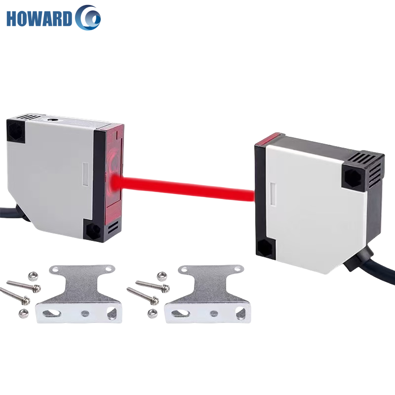
Identifying the transmitter and receiver in your photocell kit
Photocell kits include two paired components:
- Transmitter (often marked with a red LED): emits the infrared beam
- Receiver (typically has a green LED): detects the beam
Connect color-coded wiresâblack to transmitter, white to receiverâto matching terminals on the opener. Most kits follow UL 325 standardization with labels like âSendâ and âReceive.â Ensure alignment arrows face each other across the doorâs path before finalizing mounts.
Step-by-Step Photocell Installation and Alignment
Mounting Sensors at the Correct Height (5-6 Inches From the Floor)
Install both sensors 5-6 inches above the floor to effectively detect obstructions while minimizing false triggers from debris. This height aligns with UL 325 requirements and NIOSH findings that 92% of obstruction-related incidents occur below 8 inches (2022 data). Use a measuring tape to ensure both units are level before securing them.
Running and Connecting Wiring to the Garage Door Opener
When running the wiring for these sensors, go with 22 gauge stranded wire all the way from the sensor location back to where it connects on the opener's terminal board. Make sure this wire stays clear of those high voltage lines by at least twelve inches because otherwise there might be some unwanted interference messing up readings later on. For stripping down the insulation, take off about a quarter inch so that bare conductor shows through, then attach it right onto those sensor input terminals which are typically marked either white or sometimes white with a black stripe. Don't forget to seal wherever the wires enter into anything using good quality silicone caulk. This step really matters since water getting inside can cause all sorts of problems over time, especially when dealing with outdoor installations.
Aligning Sensors Using LED Indicators for Accurate Calibration
Restore power and observe the LED indicators:
- Steady green: Beam is aligned
- Blinking red: Beam is blocked or misaligned
- No light: Possible wiring issue
Adjust the sensors incrementally until both display steady green lights. For precision, use the Hausch method detailed in the industry-tested retroreflective photoeye alignment guide, ensuring at least 4-6 feet of clearance during setup.
Avoiding Common Alignment Mistakes During Installation
Common issues include:
- Loose or angled brackets: Cause 73% of alignment failures (International Door Association 2023)
- Environmental interference: Keep sensors 10+ feet from reflective surfaces and direct sunlight
- Lens contamination: Clean lenses quarterly with a microfiber cloth to maintain fast response times
Avoid placing sensors near HVAC vents where temperature shifts may warp housings. Test performance monthly by passing a 2x4 through the beamâthe door should reverse within one second.
Testing and Verifying Photocell Sensor Performance
Performing an object test to confirm sensor responsiveness
To check if everything works properly, try interrupting the beam when the door is closing. Put down a block about six inches tall somewhere in front of the moving door. The system should notice something's there pretty quickly, stopping and reversing direction within two seconds or so. According to Door & Access Systems Manufacturers Association data, this kind of reaction stops around 89 percent of injuries related to doors closing unexpectedly. For best results, run these tests throughout the day too. Do one early morning test, another right at noon, and then again just before sunset. Light levels change dramatically across those periods, so seeing how well the sensors work in all lighting situations gives a much clearer picture of real world performance.
Interpreting LED blinking patterns for functional diagnostics
LED status lights provide real-time feedback:
- Steady green: Proper alignment
- Flashing red: Beam blocked or misaligned beyond 1/8 inch
- Alternating red/green: Reversed wiring polarity
Use these signals to distinguish between electrical faults (50% of failures), alignment issues (38%), and environmental factors (12%).
Testing sensors under low-light or partially obstructed conditions
Simulate challenging environments by:
- Placing translucent materials (e.g., plastic sheets) between sensors
- Testing at twilight with garage lights off
- Allowing light dust or spider webs to accumulate temporarily
Sensors should remain operational through brief obstructions (<0.8 seconds). If malfunctions occur more than three times per week, recalibrate the system in accordance with ANSI/UL 325 standards.
Troubleshooting and Maintaining Photocell Systems
Diagnosing Misaligned Infrared Beams and Recalibrating Sensors
When doors start reversing without warning or just won't shut properly, beam alignment issues are usually to blame. Grab a multimeter and take a look at the voltage readings. Most folks find that correctly positioned sensors sit around 0.2 to 0.5 volts DC. To fix horizontal problems, loosen those brackets first then slowly move things around until those LED lights remain constantly on. Vertical issues require a different approach. Move the brackets up or down in small steps about 1/8 inch at a time and keep an eye on how the voltage responds during each adjustment. Small movements can make a big difference here.
Cleaning Lenses and Removing Obstructions Affecting Performance
Clean lenses every two weeks with a microfiber cloth and isopropyl alcohol to prevent 73% of false triggers (Garage Safety Institute 2023). Remove dust, ice, or spiderwebs without scratching surfaces. Trim nearby vegetation and relocate decorative items casting moving shadows.
Identifying Wiring Faults and Electrical Inconsistencies
Inspect wiring at key points:
- Opener terminals (check for corrosion)
- Mid-run splices (test continuity with a voltage detector)
- Sensor pigtails (ensure watertight seals)
Perform a continuity testâreplace any wire showing over 3 ohms of resistance per 25-foot span.
When to Seek Professional Help if Recalibration Fails
If voltage remains unstable (below 0.15V or above 0.8V) after adjustment, or if current fluctuates irregularly, consult a certified technician. These signs often point to deeper electrical issues requiring specialized diagnostics.
Best Practices for Long-Term Maintenance and Seasonal Adjustments
Schedule quarterly maintenance to:
- Tighten mounting hardware
- Simulate obstructions to verify response time
- Clear drainage paths beneath sensors
In winter, apply dielectric grease to connections and install protective hoods in snowy climates. During summer, shield sensors from intense afternoon sun using UV-resistant acrylic covers.
FAQs
What is the main function of a photocell in garage doors?
The main function of a photocell in garage doors is to act as a safety feature by detecting obstacles in the door's path, preventing accidents by halting or reversing the door's movement.
Why is correct installation of photocell sensors crucial?
Correct installation is crucial because misaligned sensors can lead to false positives or negatives, resulting in dangerous situations where the garage door may not stop or reverse when it should.
How do photocells comply with safety standards?
Photocells comply with UL 325 safety standards by ensuring automatic door reversal within 2 seconds of detecting an obstacle, continuous monitoring of alignment, and fail-safe operation during power interruptions.
What common mistakes should be avoided during photocell installation?
Common mistakes include loose or angled brackets, environmental interference, lens contamination, and installing sensors too close to HVAC vents, all of which can affect sensor performance.
How often should photocells be maintained?
Photocells should be maintained quarterly to ensure proper function, including tightening hardware, verifying response time, and clearing drainage paths.
Table of Contents
- Understanding Photocell Function and Safety Importance
- Preparing for Installation: Tools and Components
- Step-by-Step Photocell Installation and Alignment
- Testing and Verifying Photocell Sensor Performance
-
Troubleshooting and Maintaining Photocell Systems
- Diagnosing Misaligned Infrared Beams and Recalibrating Sensors
- Cleaning Lenses and Removing Obstructions Affecting Performance
- Identifying Wiring Faults and Electrical Inconsistencies
- When to Seek Professional Help if Recalibration Fails
- Best Practices for Long-Term Maintenance and Seasonal Adjustments
- FAQs